

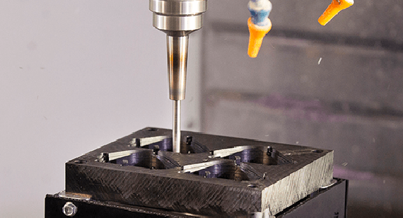

In part one of our three‑part blog series, we looked at the rules of design for manufacturing (DFM) for the injection moulding process—specifically, what validation checks you can run in SOLIDWORKS before you send your design off for manufacturing. This instalment looks at CNC machining and how SOLIDWORKS can help to speed up your overall design process.
When it comes to CNC milling, it seems like it should be fairly simple to identify any features that cannot be machined. The process of starting with a block of material and cutting away sections from the outside working in should be straightforward. Inevitably though, there is more to it than that. Deep holes with a small diameter are very difficult to achieve since the tool to create them would be very prone to breaking. Sharp internal corners are also a challenge as most cutting tools are round.
At Konlida, our CNC machining services are backed by decades of experience and advanced 5‑axis DMG MORI and MAZAK equipment. Understanding the design rules for machinability is essential for reducing cost and lead time—and SOLIDWORKS tools can help you validate your design before you ever upload a file.
For a comprehensive overview of design rules for CNC machining, see our design for manufacturing toolkit .
Analyse Manufacturability with DFMXpress
As machined parts get more complex, they are not always that easy to check visually. Handily, with SOLIDWORKS, you have DFMXpress . This is on the Tools drop‑down menu under Xpress Products and also in the Evaluate tab on the CommandManager. This can check your design’s suitability for multiple manufacturing processes including Mill/Drill, Turning with Mill Drill, Sheet Metal, and Injection Moulding.
Out of the box, DFMXpress is set up with industry‑recommended values but it is completely customisable based on what you can achieve in‑house or with your manufacturer. For Mill/Drill, DFMXpress will run 10 checks for manufacturability:
- It checks the hole‑depth‑to‑diameter ratios of all the holes in the part.
- It looks for inaccessible features that could not be reached by the milling cutter.
- It identifies sharp internal corners , deep pockets and slots , holes with flat bottoms, and fillets/rounds on outside edges.
- It looks for holes that are not standard sizes and if any holes or cutouts go all the way through the part—which could damage the CNC mill’s bed or require a second set‑up to cut from the other side as well.
Every check your design fails will be categorised, and each fail is listed individually. Clicking on each one highlights where it is in the part.
These DFM checks align closely with our own internal analysis. When you upload a CAD file to Konlida, our automated quoting system performs similar manufacturability analysis—identifying features such as undercuts, thin walls, deep pockets, and unfavourable hole geometries. For more on what we check for, see our 3 gate considerations to improve mouldability and draft angle guidelines guides.
At any stage, you can modify the part design and re‑run the DFMXpress checks. The fewer failed checks, the easier—and therefore usually cheaper—the design will be to produce. If you want to understand the milling or turning process even better, you could start to set up and simulate toolpaths using SOLIDWORKS CAM.
For guidance on optimising your CNC designs for cost and manufacturability, see our understanding injection mould cost for parts and tooling guide—many of the same principles apply to CNC machining as well.
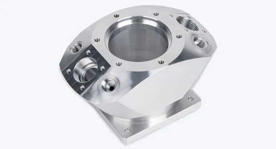
Summary of DFMXpress Checks for CNC Machining
| Check | What It Identifies | Why It Matters |
|---|---|---|
| Hole depth‑to‑diameter ratio | Deep, small‑diameter holes | Tools may break; may require EDM |
| Inaccessible features | Features unreachable by cutter | May require special tooling or multiple set‑ups |
| Sharp internal corners | Square corners in pockets | Requires EDM or corner relief |
| Deep pockets and slots | Excessively deep features | Long tools deflect; poor surface finish |
| Non‑standard hole sizes | Holes that require special tooling | Increases cost and lead time |
| Through‑holes | Holes that could damage the machine bed | May require second set‑up or sacrificial material |
Stay Tuned
Stay tuned next week for our final look at how you can leverage SOLIDWORKS to improve manufacturability on 3D‑printed parts . In the meantime, if you are ready to get your CNC machined part quoted, upload your CAD file for a free DFM analysis and quote.
About the Author
Mark Rushton is a product portfolio manager for SOLIDWORKS, in the Desktop products team, focused on additive manufacturing. He has been involved with 3D CAD and 3D printing for over 15 years in several capacities—from research to consulting for leading engineering firms. This article was originally published in collaboration with Konlida Precision Technology.
Need Help with Your CNC Machining Design?
Konlida’s applications engineering team can help you optimise your design for manufacturability—whether you are using SOLIDWORKS, Fusion 360, or any other CAD platform.