Design for Machining Toolkit
Get in-depth design advice to optimize your plastic and metal parts for CNC machining. Designing with machining in mind can accelerate production time and reduce production costs
Certifications ISO 9001:2015 | ISO 13485:2016 | AS9100D | IATF 16949
Optimizing Part Design for Machining
There are many design considerations involved when creating CNC machined plastic and metal parts. You can design for cost, design for quality, design for assembly, or design for manufacturability, but navigating that landscape can be challenging, at times. At Konlida, we provide automated design analysis on CAD models that highlights features in your part design that can be adjusted for manufacturability. It’s a great design resource to have at your fingertips. To keep those manufacturability advisories at a minimum and optimize your part design, we created this helpful kit detailing different CNC machining resources.
Designing for Machined Parts
Navigating Critical Machining Advisories
Designing for Machinability
CNC machining has been around for decades, and for good reason. It’s one of the fastest manufacturing technologies for prototypes and end-use parts. Want to learn how you can optimize your product development cycles with CNC machining? Our white paper shares how to design for this subtractive manufacturing process, select the best material for your application, and streamline new product development.
Optimizing your part for CNC Machining
Manufacturing both prototypes and production parts quickly and cost-efficiently is often a balancing act between on-demand CNC machining capabilities and an optimized part designed for those capabilities. When working with Konlida’s milling and turning processes, there are a handful of important design considerations that can accelerate production time while reducing costs.
Design Guidelines for Common Features
Tolerances
Tolerances represent dimensional accuracy of a part. It is the amount of acceptable variance in the dimension of a part. Typically, Konlida will maintain a general machining tolerance of ±0.005 in. (±0.13mm), but if tighter tolerances are needed we suggest our network partners who can achieve down to ±0.002 in. (±0.05mm). The best thing about a standardized general tolerance of ±0.005 in. (±0.13mm) is you don’t need to produce a 2D drawing. We can start manufacturing as soon as you have the 3D model.
Holes
In general, at Konlida, most holes are interpolated with an end mill rather than drilled. Apart from allowing for greater flexibility in hole sizes this also offers better surface finishes than drilled holes. The same tool is used for slots and pockets, too, which means a reduction in cycle time and part cost. The principal trade-off is that holes more than six diameters deep become challenging as they normally need specific drills, which may mean the part must be machined from both sides.
Threading
We take a more modern approach to thread-making, rather than using traditional "taps" to create a thread manually. We use a single-point thread mill to helically cut the thread profile. This CNC process produces an accurate thread, and a single tool can be used to cut multiple threads that share the same pitch (number of threads per inch). UNC and UNF threads from #2 up to 0.5 in. (12.7mm) and metric threads from M2 to M12 are possible within a single tool set. Check out the full list.
Text
Konlida is capable of machining text. Here are our recommended text specifications for CNC milling:
- Plastic and soft metals: Minimum width of 0.018 in. (0.457mm), depth of 0.0118 in. (0.3mm).
- Hard metals: Minimum width of 0.033 in. (0.838mm) and depth of 0.0118 in. (0.3mm).
- If the design permits it, opt for recessed vs. raised text.
- Fonts with radii: this includes Arial, Verdana, sans-serif or similar because these work best with circular tools.
- 20 point or larger type, to ensure the text widths are greater than minimum requirements.
Walls and Features
Konlida toolsets are made with materials such as tungsten carbide, a super rigid material that offers maximum tool life and productivity with minimal deflection. But even the strongest tools deflect, as do metals and plastics as they are machined.
Minimum feature thickness in the Konlida factory is ±0.005 in. (±0.13mm). If you have a feature that is 0.020 in. (0.51mm) or smaller, our automated quoting system will highlight it as a thin-wall geometry. Any thin walls that are 0.020 in. (0.51mm) or less are not only subject to breakage during the machining operation, but may flex or warp afterwards. Beef them up as much as your part design allows.*
Radii
As a part of the CNC machining process, sharp corners on a part will be radiused (rounded). This will be identified before the part is milled. In softer materials, tools are flat bottomed so only the tool diameter needs to be considered. In harder metals, it is typical for tools to have a tip radius that will leave a small radius in the bottom of pockets.**
Notes:
* Try adding steps to buttresses to stiffen your design. Watch out for deep, narrow pockets, or part features situated alongside tall walls. Cutter or workpiece vibration could cause deflection, and a loss of accuracy or surface finish.
** Generally, radii are a good thing, fillets spread loads well, sharp corners can act as stress raisers and can initiate fatigue cracks. We deburr every part, but if you are considering adding external radii to improve cosmetics and handling, a 45° chamfer is quicker to machine and considerably more cost effective.
Remember for CNC:
- Internal corners—fillet or radii
- External corners—chamfer
Any part that requires square corners will cost much more, as the only way to produce them is to burn them out with electro-discharge machining (EDM) or to cut slowly with extremely small tools.
Navigating Critical Machining Advisories
Material Left Behind
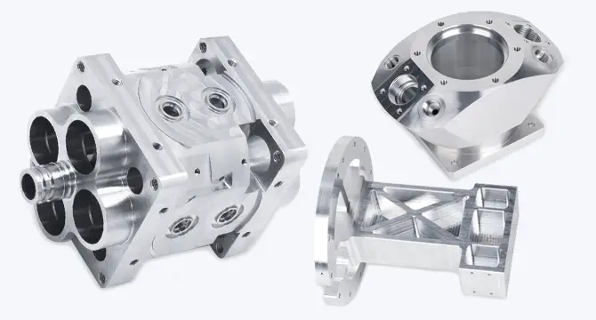
Our analysis will advise you regarding what percentage of material will be milled and what will remain un-milled, deviating from your original design. Dark blue areas arethose where material will be left behind or indicate where features will not be formed. You can decide whether to modify your design or leave it as is.
Reasons for inaccessible material come in two categories:
- General design for CNC: For example, deep holes, galleries or internal features, deep threads, undercuts that can’t be reached, or tool access all may push the limits of any CNC process and might be candidates for 3D printing.
- Trade-offs to manufacture quickly: Holes deeper than x6 diameter, threads deeper than x3 diameter, undercuts that need special tools (t-cutters, woodruff cutters or Lollipop Cutters), large 5-axis parts or restricted tool access can all leave material behind. This is because we stock a standardized toolset. We are always happy to offer advice, and have a huge range of CNC capabilities available via Konlida Network.
Holes That Can Be Threaded
As part of your design analysis, you can highlight and assign holes that need threads. It’s as easy as clicking on your 3D model.
We offer a selection of metric and imperial (UNF, UNC) threads, along with coil and key inserts. However, we do not install or supply inserts.
To make a hole eligible for threading it must be modeled at the pilot-drill diameter. Our automated design analysis will detect eligible threads, enabling you to pick them one-by-one or all of them in seconds.
Too Thin
Standard part tolerance at Konlida is ±0.005 in. (±0.13mm). For features that are smaller than 0.020 in. (0.51mm), the quoting system will highlight these automatically as a thin wall geometry. You should keep in mind that we'll still allow it to be machined, but the machined part may differ slightly from your original design. Any walls thinner than 0.020 in. (0.51mm) risk breakage during machining, and flex or warp afterwards. Whenever possible, we advise thickening them.
Part Too Large
Maximum extents refers to the raw material and machining envelope. Depending on part geometry and fixturing/clamping requirements, the maximum part size may be slightly smaller. For every upload we will analyze and provide feedback.
Find out the max extents for each material we stock at Konlida.
Get an online quote and manufacturing analysis today.
Enhanced Machining Capabilities with Our Konlida Network
Get anodizing, tighter tolerances, and volume pricing options through our network of manufacturing partners. You'll find plating (black oxide, nickel), anodizing (Type II, Type III), and chromate coating at scale; tolerances down to ±0.020mm; and cost-efficient machined parts at higher volume.
CNC Machining
Over 30 plastic and metal machining materials are available for functional prototypes and end-use parts in as fast as 1 day.
Konlida Q&A: CNC Optimisation
In this on-demand episode we answer your questions on CNC Optimisation with David Ewing, EMEA Product Manager - CNC Machining at Konlida.
How to Reduce CNC Machining Costs
Incorporate these design and material ideas to simplify your CNC machining design, and lower expenses.
Get an online quote and CNC machining design analysis today.