


Improve the appearance and performance of injection‑moulded parts by eliminating cosmetic issues early
As with any manufacturing process, injection moulding comes with its own set of design guidelines. Design engineers who understand these best practices will increase their chances of developing structurally sound and cosmetically appealing parts and products.
At Konlida, our Injection Moulding services are backed by decades of experience and thousands of moulds manufactured. This guide covers common cosmetic defects that occur on plastic injection‑moulded parts and provides practical tips on how to avoid them, drawing on our Design for Manufacturing toolkit for deeper guidance.
Sink Marks
As its name implies, sink appears as a dimple or shallow depression on the surface of a moulded part. It is caused by thicker‑than‑normal cross‑sections, non‑uniform part design, or improper gate placement—the doorway through which hot plastic first enters the mould cavity.
Some plastics—polypropylene and acetal, for example—are very susceptible to sink, whereas fibre‑ and glass‑filled materials are less prone to sink.
How to avoid it: Follow our Wall Thickness Guidelines , which recommend that a workpiece minimum wall thickness be no less than 40 to 60 percent of its thickest section. Material flow within the mould should travel from thick to thin whenever possible, which may mean reorienting the mould cavity or placing the gate away from cosmetic surfaces.
Warpage
Design a part with walls too thin for the target material and it is likely to curl up like a potato chip. This is called warp and is easily avoided by following the same rules used with sink, namely staying within the general wall thickness guidelines found in our Wall Thickness Guidelines .
Ironically, the glass‑filled materials that work well with sink‑prone parts are more susceptible to warp. That is because, as the part cools, the glass fibres tend to line up in the same direction, creating internal stresses.
Parts with internal support structures—gussets to support thin walls, or ribbing of large flat surfaces—fare best against warp. For detailed guidance on adding structural features, refer to our Design for Manufacturing toolkit .
Drag or Scrape Lines
Sufficient draft is an important part of any mould design, and quick‑turn tooling is no exception. Vertical walls—those part surfaces parallel to the direction of mould operation—should have a minimum draft angle of 0.5°, and 2° is even better. Heavily textured surfaces may require 5° or more.
Without proper draft, part ejection becomes difficult if not impossible, and drag or scrape lines will occur. For comprehensive guidance on applying draft to your parts, see our Draft Angle Guidelines , which explains the relationship between draft, surface finish, and ejection quality.
Flash
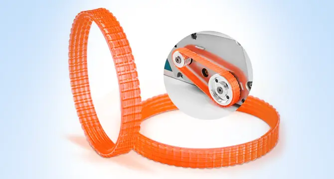
Look closely at a rubber O‑ring and you will see a thin line of material at its outermost periphery. That is a parting line, the seam where the two halves of the mould come together.
With free‑flowing materials such as Santoprene or unfilled nylon, a small amount of flash can sometimes ooze into the seam and often requires trimming once the part has cooled.
On a donut shape such as this, there is little choice over the parting‑line location, but many orthogonal parts have sharp corners which make a clean, crisp junction at which the mould can separate. Flash or no flash, you should expect a parting line on most moulded products. Konlida identifies the parting line location in your quote and may suggest ways of modifying part geometry to avoid flash.
The relationship between gate design and flash is also discussed in our 3 Gate Considerations to Improve Mouldability guide.
Swirling
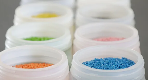
From Honey Beige to Cornflower Blue, Konlida stocks standard colourants. These are mixed with natural resin pellets immediately prior to the moulding run and are usually quite close to the target colour, but the final product may vary due to the polymer being used, texture and polish of the tool, and swirling during the mixing process.
If you require an exact colour match, it is best to purchase colour‑matched, pre‑compounded resin from an external vendor. Konlida accepts most customer‑supplied resins. For help selecting materials with the right colour and performance characteristics, see our Materials Comparison Guide .
Knit Lines
Those fine lines that look like hairline cracks in your injection‑moulded part are knit lines—formed when two opposing flows of material join together in the mould cavity. Commonly seen at the edge of a hole or other cored feature, knit lines are typically purely cosmetic.
However, knit lines may create a physical failure point if present in an area that receives substantial stress, such as the head of a screw. In this case, designing a strengthening boss feature around the hole is a good precaution, or you can skip the hole entirely and drill it afterwards.
Depending on the resin, resin temperature, mould temperature, and filling speed, knit lines can vary from virtually invisible to something that looks like cracks in the plastic. The relationship between knit lines and gate placement is explored further in our 3 Gate Considerations to Improve Mouldability guide.
Gate Vestige
Gate vestige is the small mark left at one end of the part by removal of the gate after moulding—usually with a side cutter or razor knife. It is an unavoidable fact of injection moulding.
The only thing that can be done to avoid it is orienting the part in the mould such that cosmetic surfaces are unaffected. When moulding a statue replica, for example, the gate should be placed on a hidden surface.
When submitting a design to Konlida, always be sure to speak to our applications engineering team to ensure surfaces that require a vestige‑free appearance can be accommodated. We may have options to change a gate style depending on the material and part geometry. It is much easier to address this during the review stage rather than after mould design has begun. For more on gate types and their impact on part appearance, see our 3 Gate Considerations to Improve Mouldability guide.
Jetting, Orange Peel, Splay, and Blush
Several miscellaneous problems can crop up with injection moulding, many of which can be traced back to wall thicknesses that exceed general recommendations:
| Issue | Appearance | Primary Cause |
|---|---|---|
| Jetting | Worm‑like swirl near thick gate areas | Temperature variations within the material flow |
| Orange peel | Surface texture resembling citrus peel | Flow variations in the mould cavity, usually in thicker sections |
| Splay | Silvery streaks and material flaking | Moisture, degraded resin, or material shear from excessive injector‑screw speeds |
| Blush | Cloudy discoloration near gate areas | Improper fill speeds (part geometry and gate placement also play a role) |
Thankfully, most of these issues can be resolved through slight modifications to part design or selecting a different material. Difficult part geometries often require fine‑tuning of moulding temperature, injection speed, hold times, or all three.
Material selection also plays a big part in cosmetics. Polypropylene and HDPE tend to sink more than polybutylene or acetal, but flow better into small part details. For help with material selection, visit our Materials Comparison Guide .
Surface Finish Options
If you select a PM‑F0 non‑cosmetic finish on a tool, the finished part will likely show small, circular, end‑mill marks and tool transition lines. If you need a surface finish that is more cosmetically appealing, it is generally a simple—if more expensive—matter to manually polish the tool.
| Finish | Description | Best For |
|---|---|---|
| PM‑F0 | Non‑cosmetic, as‑machined | Functional parts where appearance is not critical |
| PM‑F1 | Low‑cosmetic, most toolmarks removed | Parts requiring moderate cosmetic appearance |
| SPI‑A2 | High‑polish (mirror) finish | Clear, glossy, or highly cosmetic surfaces |
| PM‑T1 / T2 | Bead‑blasted texture | Matte appearance, hiding minor cosmetic marks |
Bear in mind that deep slots and cavities are difficult to reach for polishing and texturing, and fine finishes may impact quick turnaround time because of the additional effort needed. For a complete overview of surface finish options—and how finish selection affects draft requirements—see our Surface Finishing Options page.
In addition to these eight surface finish options, Konlida also offers mould texturing and part marking services such as pad printing and laser engraving.

Summary
| Defect | Primary Cause | Key Prevention |
|---|---|---|
| Sink | Thick sections, non‑uniform walls | 40–60% wall thickness ratio |
| Warp | Thin walls, material orientation | Uniform walls, support structures |
| Drag | Insufficient draft | 0.5°–2° draft minimum |
| Flash | Material seepage at parting line | Clean shutoff, geometry optimisation |
| Swirling | Inconsistent mixing | Pre‑compounded colourant |
| Knit lines | Merging flow fronts | Optimise gate location, strengthen bosses |
| Vestige | Gate removal | Orient part to hide gate mark |
| Jetting / Orange peel / Splay / Blush | Flow and temperature variations | Optimise design, material, process parameters |
Need Help with Your Injection Moulding Design?
The good news is that Konlida has extensive experience in injection moulding and can help you avoid cosmetic defects before tooling begins. Our free online design analysis on your uploaded CAD model provides valuable recommendations on improving manufacturability, and our applications engineering team is always available to help.