


What is Multi Jet Fusion?
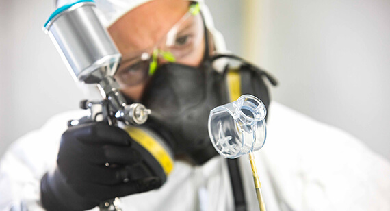
Multi Jet Fusion (MJF) is an industrial powder‑bed fusion 3D printing technology that produces durable, production‑grade thermoplastic parts without the need for tooling. MJF has rapidly gained adoption across industries ranging from automotive and aerospace to medical devices and consumer goods.
Unlike traditional manufacturing methods such as CNC machining or injection moulding, MJF requires no hard tooling—making it an attractive option for prototyping, bridge production, and low‑to‑mid‑volume manufacturing. Its ability to produce complex geometries with consistent mechanical properties positions it as a viable alternative to both additive and conventional manufacturing processes.
At Konlida, MJF is one of the key technologies within our 3D printing services , offering engineers a production‑ready solution for nylon‑based parts.
How MJF Works
MJF builds parts layer by layer, but the process differs significantly from other additive manufacturing technologies.
The MJF process sequence:
- Powder spreading – A thin layer of thermoplastic powder (typically nylon) is evenly distributed across the build platform.
- Agent deposition – An inkjet array moves across the powder bed, precisely depositing two types of agents:
- Fusing agent – applied where the part is to be solidified
- Detailing agent – applied along part boundaries to improve edge definition and surface quality
- Fusing – An infrared heating element passes over the entire layer, simultaneously fusing the areas where the fusing agent was deposited. The detailing agent modifies the fusing process to create fine details and smooth surfaces.
- Layer repetition – The build platform lowers, a new layer of powder is spread, and the process repeats until the part is complete.
- Cooling and unpacking – The entire powder bed cools gradually, after which the parts are unpacked from the surrounding unsintered powder, which acts as a natural support structure.
Because the surrounding powder supports the part during printing, MJF does not require dedicated support structures—enabling complex internal channels, lattice structures, and intricate geometries that would be difficult or impossible with other processes.
For more detail on MJF capabilities, explore our MJF 3D printing guide .
Technical Specifications
| Parameter | Specification |
|---|---|
| Maximum build size | 380 × 284 × 380 mm |
| Layer thickness | 80 µm (0.08 mm) |
| Minimum feature size | 0.5 mm |
| Minimum wall thickness | 0.5–0.7 mm |
| Dimensional accuracy | ±0.3% with a lower limit of ±0.3 mm |
| Print resolution (X, Y) | 1200 dpi |
| Lead time | From 3 business days |
Dimensional accuracy in practice:
For well‑designed parts, tolerances of ±0.30 mm plus 0.1% of nominal length can typically be achieved. This means a 100 mm part would have a tolerance of approximately ±0.40 mm. Note that tolerances may change depending on part geometry.
Isotropy: MJF parts exhibit near‑isotropic mechanical properties, meaning strength is consistent across all axes—a critical advantage over FDM where layer‑to‑layer bonding is typically weaker.
Material Options and Performance Data
MJF is primarily associated with nylon‑based (polyamide) materials, offering an excellent balance of strength, toughness, fatigue resistance, and dimensional stability.
PA 12 Black (Nylon 12)
| Property | Value |
|---|---|
| Density | 1.01 g/cm³ |
| Tensile Strength | 48–50 MPa |
| Tensile Modulus | 1,700–1,900 MPa |
| Elongation at Break | 8.5–20% |
| Heat Deflection (1.8 MPa) | 95°C |
| Heat Deflection (0.45 MPa) | 175°C |
| Impact Strength (notched) | 5 kJ/m² |
PA 12 Black is the best material option for designs that incorporate living hinges. It offers near‑isotropic mechanical properties and is an economical material choice.
PA 12 40% Glass‑Filled Black
| Property | Value |
|---|---|
| Tensile Strength | 30 MPa |
| Tensile Modulus | 2,500–3,500 MPa |
| Elongation at Break | 6.5–10% |
| Heat Deflection (1.8 MPa) | 121–174°C |
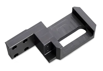
Glass‑filled PA 12 offers the highest stiffness in the MJF catalogue at 2.5 GPa tensile modulus. Use it for structural brackets, housings under load, and applications where it can replace machined aluminium at lower weight and cost. The primary benefit is heat deflection at 175°C.
Material Selection Guide
| Requirement | Recommended Material |
|---|---|
| General purpose, good strength | PA 12 Black |
| High stiffness, structural applications | PA 12 40% Glass‑Filled |
| Highest ductility, impact resistance | PA 11 |
| Flame retardancy | Flame‑retardant nylon grades |
| High heat deflection | PA 12 Mineral‑Filled |
For a complete overview of available materials, visit our 3D printing materials guide .
Design Guidelines for MJF
Proper design is essential to maximise part quality, reduce cost, and ensure successful printing and powder removal.
Wall Thickness
| Feature | Recommended Minimum |
|---|---|
| General wall thickness | 0.5–0.7 mm |
| For larger parts (>178 mm) | 3.2 mm recommended to ensure stability |
| Fine vertical features | ≥ 1.2 mm |
Why these values? MJF can achieve 0.5 mm walls because the detailing agent modifies fusing along part boundaries, creating sharper edges and allowing thinner structures without collapse. However, thinner walls increase the risk of warpage, particularly on larger parts.
Clearances and Gaps
| Feature | Recommended Clearance |
|---|---|
| Between assembled parts | 0.2–0.4 mm |
| Between moving parts | 0.6 mm minimum |
| For thick walls (>50 mm) | 0.9 mm minimum |
Holes and Channels
- Minimum hole diameter: 2 mm (recommended for powder removal)
- Include at least two openings for effective powder evacuation from internal cavities
- Internal channels are possible but require careful design for powder removal
Text and Embossing
| Feature | Recommendation |
|---|---|
| Embossed text (flat) | ≥ 1.5 mm wall thickness |
| Engraved details | 0.5 mm deep × 0.5 mm wide minimum |
Warpage Prevention
Larger part sizes (>178 mm) and parts with thin features are the most susceptible to warp. To minimise warpage:
- Maintain uniform wall thickness
- Consider symmetrical part geometry
- Add structural ribs where possible
- For parts exceeding 178 mm, use 3.2 mm wall thickness as a baseline
For comprehensive design guidance, refer to our Design for Manufacturing toolkit .
Post‑Processing Options
MJF parts typically require post‑processing to achieve the desired surface finish and appearance.
| Finish | Description | Best For |
|---|---|---|
| As‑printed (grey) | Smooth surface without visible layers, powder texture | Functional prototypes where appearance is not critical |
| Dyed (black) | Parts immersed in a warm colour bath; colour reaches ~0.5 mm depth | Production parts requiring uniform black colour |
| Tumble smoothing | Parts tumbled in ceramic chips; creates polished finish similar to injection moulding | Parts requiring improved surface finish and reduced roughness |
| Vapour smoothing | Parts exposed to solvent vapour; creates even glossy finish | Cosmetic parts requiring high‑quality appearance |
For more finishing options, see our surface finishing guide .
MJF vs. Injection Moulding: A Benchmark Comparison
For engineers evaluating MJF, the natural benchmark is injection moulding—the industry standard for producing plastic parts at scale. Understanding where MJF fits relative to injection moulding is critical for informed decision‑making.
Performance Comparison
| Property | MJF PA12 | Injection‑Moulded PA12 |
|---|---|---|
| Tensile Strength | 48–50 MPa | 50–55 MPa |
| Elongation at Break | 15–20% | 20–30% |
| Tensile Modulus | 1,700 MPa | 1,800–2,200 MPa |
| Isotropy | Near‑isotropic | Fully isotropic |
| Surface Roughness (Ra) | 0.8–1.6 µm (as‑printed) | <0.4 µm (moulded) |
| Dimensional Tolerance | ±0.3 mm + 0.1% | ±0.05–0.1 mm |
Key performance characteristics:
- MJF‑PA12 specimens show static properties comparable to conventional PA12
- The fatigue strength of MJF‑PA12 is similar to injection‑moulded PA12
- MJF‑printed polypropylene achieves mechanical properties that compare favourably with injection‑moulded samples
When to Choose MJF Over Injection Moulding
| Factor | MJF | Injection Moulding |
|---|---|---|
| Tooling cost | None | High (€5,000–€50,000+) |
| Lead time | 3–5 days | 4–12 weeks (tooling) |
| Minimum quantity | 1 part | 500–1,000 parts (economical) |
| Geometry complexity | Unlimited (channels, lattices, undercuts) | Limited by mould design |
| Design iteration | Fast (update CAD, re‑print) | Slow (re‑tool required) |
| Per‑part cost | Higher (economies of scale) | Lower (amortised tooling) |
| Material options | Limited to nylon‑based | 100+ resins |
Recommendation: MJF is ideal for bridge production—producing functional parts while injection moulding tooling is being manufactured. It also excels when part quantities are too low to justify tooling investment (typically <500 parts) or when geometry is too complex for moulding.
Strength Relative to Injection Moulding
| Metric | MJF PA12 vs. Injection‑Moulded PA12 |
|---|---|
| Tensile strength | ~90–95% of injection‑moulded values |
| Stiffness | ~85–90% of injection‑moulded values |
| Surface finish | Rougher (requires post‑processing for cosmetic applications) |
Key takeaway: MJF parts typically achieve 85–95% of injection‑moulded mechanical performance, making them suitable for functional prototypes and many end‑use applications. The primary compromises are surface finish and per‑part cost, not mechanical integrity.
All MJF services at Konlida are backed by ISO 9001 and AS9100D quality certifications , ensuring consistent quality across every build.
MJF vs. SLS: A Technical Comparison
Both MJF and Selective Laser Sintering (SLS) are powder‑bed fusion technologies using nylon materials, but they differ in significant ways.
| Aspect | MJF | SLS |
|---|---|---|
| Fusing method | Infrared heating + fusing agent | Laser tracing each point individually |
| Print speed | Faster (entire layer fused simultaneously) | Slower (point‑by‑point) |
| Surface finish | Smoother, finer detail | Rougher, more textured |
| Feature resolution | 0.5 mm | 0.75 mm |
| Small feature accuracy | ±0.10 mm | ±0.025 mm (better for tiny features) |
| Layer thickness | 0.08 mm | 0.1 mm |
| Tolerances | ±0.30 mm + 0.002 mm/mm | ±0.20 mm + 0.002 mm/mm |
| Materials | PA 11, PA 12, PA 12 GB, TPU | PA 12, PA 12 CF, PA 12 GF, TPU |
| Powder reusability | Up to 80–95% | Typically 50–70% |
| Cost | Lower for higher volumes | Higher for higher volumes |
Key considerations for choice:
- Choose MJF when surface finish, fine detail, production speed, and batch consistency are priorities
- Choose SLS when lower cost for small volumes, specific material properties, or extremely fine small features are required
Cost Considerations
Cost depends on part size, geometry, quantity, and material requirements.
| Factor | MJF | FDM | SLS |
|---|---|---|---|
| Typical cost (small‑medium part) | €5–10 per cm³ | Lower | Higher |
| Best quantity range | 50+ parts | 1–10 parts | 10–50 parts |
| Tooling cost | None | None | None |
| Post‑processing cost | Moderate | Low | Moderate‑high |
When MJF is most economical:
- Part quantities exceed 50 units
- Parts can be densely nested in the build chamber
- Complex geometries require support structures with other technologies
- Surface finish and detail resolution are important
When FDM may be more economical:
- Very low quantities (1–10 parts)
- Large parts
- Specialised engineering thermoplastics required
Cost structure: MJF costs include fusing agent and detailing agent consumption rates, as well as material costs. Powder recyclability of up to 95% helps reduce material waste.
Ready to compare costs for your specific project? Request an instant quote to evaluate options.
Applications and Use Cases
MJF is suitable for a wide range of applications across multiple industries.
| Application | Why MJF | Example Materials |
|---|---|---|
| Functional prototypes | Production‑grade material properties | PA 12 |
| End‑use production parts | 50–5,000+ parts per year, no tooling | PA 12, Glass‑filled |
| Housings and enclosures | Complex geometries, good surface finish | Glass‑filled PA 12 |
| Brackets and structural components | High stiffness, heat resistance | Glass‑filled PA 12 |
| Jigs and fixtures | Accuracy, repeatability | PA 12 |
| Medical devices | Biocompatibility (USP Class I‑VI, FDA compliant) | PA 12 |
| Automotive components | Heat resistance, durability | Glass‑filled PA 12 |
| Lightweighting applications | Lattice structures, complex geometries | PA 12 |
Watertight applications: MJF PA 12 can produce parts suitable for watertight applications, making it suitable for fluid handling components.
For industry‑specific applications, visit our medical industry solutions or automotive industry solutions .
Summary
Multi Jet Fusion is a production‑grade 3D printing technology that offers a compelling combination of speed, quality, and design freedom for nylon‑based parts.
| Consideration | MJF Capability |
|---|---|
| Materials | PA 12, PA 11, glass‑filled, flame‑retardant |
| Typical tolerances | ±0.30 mm + 0.1% of nominal length |
| Layer thickness | 0.08 mm |
| Best for | Functional prototypes, production parts (50–5,000+), complex geometries |
| Key advantage | Speed, surface quality, near‑isotropic properties |
| Strength vs. injection moulding | 85–95% of mechanical performance |
| Design freedom | No supports, complex channels, lattices, nested parts |