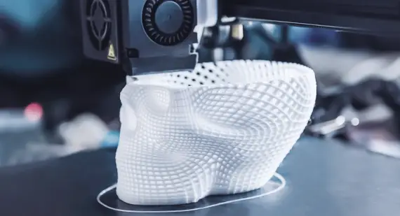
Additive manufacturing is an excellent complement or alternative to machining when irregular, intricate, or smaller tooling is required
Most manufacturers use jigs and fixtures – for good reason. They increase the accuracy, precision, reliability, and interchangeability of finished parts. Traditionally, jigs and fixtures have been CNC machined, but industrial‑grade 3D printing (additive manufacturing) is becoming more popular for this type of work. The key is choosing which technology fits a particular application.
General rule: If a jig or fixture can be machined with 3‑axis CNC, it should be machined. Machined fixtures typically offer superior surface finishes, stronger materials, and greater accuracy. For lower‑volume runs, costs and turnaround times are similar to 3D printing.
However, for jigs and fixtures with irregular or complex shapes, 3D printing can be an excellent complement or alternative – especially for smaller tools. Parts that are difficult (or impossible) to machine can sometimes be produced with 3D printing. When producing multiple jigs and fixtures, 3D printing can also help keep costs down.
Konlida offers several 3D printing technologies. The following sections will help you determine the best fit for each jig/fixture application.
Why 3D Print Jigs and Fixtures?
- Irregular or complex shapes
- Small tooling
- Parts that are difficult to machine
- Multiple parts
Stereolithography (SLA) – Popular Choice for Smaller, Complex Tooling
SLA is a good option for building smaller, complex jigs and fixtures due to the excellent surface finish achievable. Material strength and durability are limited; however, metal plating of SLA parts is a common solution for those who prefer the cost‑competitive SLA technology.
Design considerations for SLA:
- Typical tolerances: ±0.05 mm for the first 25 mm, plus ±0.001 mm per additional millimetre in X/Y.
- Z‑dimension tolerances: ±0.13 mm for the first 25 mm, plus ±0.001 mm per additional millimetre.
For detailed guidelines, refer to our SLA Design Guide.
Selective Laser Sintering (SLS) – Larger Tooling
SLS is used more regularly for larger jigs and fixtures and is a cost‑competitive choice. SLS produces durable and accurate parts that are stronger than those made with SLA. SLS also offers a larger build volume, but parts have a rougher finish and lack very fine details.
Design considerations for SLS:
- Maintain consistent wall thicknesses.
- Use radii on interior and exterior corners to prevent warping and maintain dimensional accuracy.
- Typical tolerances: ±0.25 mm plus ±0.0015 mm per additional millimetre.
See our SLS Design Guidelines for more information.
Multi Jet Fusion (MJF) – Gaining Popularity
MJF is becoming increasingly popular for producing jigs and fixtures. MJF is fast – producing functional nylon prototypes and end‑use parts in as little as one day. Final parts exhibit quality surface finishes, fine feature resolution, and more consistent mechanical properties compared to SLS (though SLS has better small‑feature accuracy).
Design considerations for MJF:
- Consistent wall thicknesses.
- Radii on interior and exterior corners to prevent warping.
- Typical tolerances: ±0.30 mm plus ±0.002 mm per additional millimetre.
Refer to our MJF Design Guidelines.
Direct Metal Laser Sintering (DMLS) – For Durability
DMLS produces jigs and fixtures that are extremely strong (near fully dense). However, DMLS surfaces tend to be rough, and turnaround times are longer because post‑processing often includes secondary machining.
Design considerations for DMLS:
- Add additional material when gradually transitioning to larger cross‑sections.
- Minimise supports to improve part quality.
- Avoid self‑supporting features with angles less than 45°.
- Large overhangs can reduce part detail or cause build failure.
- Use teardrop or diamond‑shaped channels (superior to circular) for uniform surface finish and maximum diameter.
- For flat bridges, the recommended minimum unsupported distance is 2.0 mm.
- Typical tolerances: ±0.076 mm plus ±0.001 mm per additional millimetre.
For more guidance, see our DMLS Design Guidelines.
Final Considerations When 3D Printing Jigs and Fixtures
- Produce stiffer, stronger tooling. Remember that 3D‑printed parts are typically strongest in the X‑Y draw plane compared to the Z build direction.
- Tolerances may change depending on part geometry.
- If it can be 3‑axis CNC machined, it should be machined. Use 3D printing when complexity or geometry makes machining impractical.