Consider hole depths, threading, wall thickness, and other machining capabilities to reduce production time and cost
Efficient CNC machining depends as much on good design as on capable equipment. Whether you are developing prototypes or production parts, a few disciplined choices in the design phase can significantly reduce cycle time, tool wear, and overall cost.
This guide outlines six practical design considerations for milling and turning. They are based on the capabilities of Konlida’s CNC machining centres and reflect common questions from European engineers.
- Hole depths and diameters
- Thread sizes and types
- Text and marking
- Wall heights and feature widths
- Live‑tool turning
- 3‑axis vs. 5‑axis milling
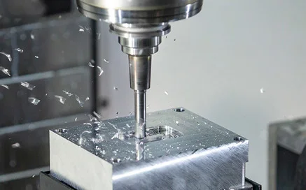
1. Hole Depths and Diameters
Most holes at Konlida are interpolated with an end mill rather than drilled. This method offers greater flexibility in hole sizes with a given tool and provides a better surface finish than drilling. It also allows the same tool to be used for slots and pockets, reducing cycle time and cost.
The main limitation is that holes exceeding six times the tool diameter in depth become challenging due to end mill length constraints. For deeper holes, we may need to machine from both sides of the part. If your design requires deep holes, please specify this clearly on your drawing so we can evaluate the most efficient approach.
For more detailed guidance, see our threading and hole‑making guidelines.
2. Thread Sizes and Types
We use thread milling rather than traditional tapping for most internal threads. Thread milling offers several advantages:
- A single tool can cut any thread size sharing the same pitch
- Better thread quality and accuracy
- Reduced setup time and tooling costs
Konlida offers a selection of UNF, UNC, and metric threads. We can also machine parts to accept coil and key inserts (though we do not supply or install inserts as standard; please contact our sales team for custom hardware requirements).
For full specifications, see our threading options page.
3. Text and Marking
If you require part numbers, descriptions, or logos on your machined parts, please observe the following guidelines:
- Minimum character spacing: 0.5 mm
- Minimum stroke width: 0.5 mm
- Text should be recessed (engraved), not raised
- Recommended fonts: 20‑point or larger, Sans‑Serif (e.g. Arial, Verdana)
Engraved text adds machining time and cost. For large‑volume production, consider alternative marking methods such as laser marking, which may be more economical. If you require laser marking or other secondary operations, please contact our applications engineering team to discuss your needs.
4. Wall Heights and Feature Widths
All of our cutting tools are carbide, offering excellent rigidity and tool life. However, even carbide tools deflect under cutting forces, and workpiece materials – especially plastics – can also deflect or vibrate during machining.
Key design limits:
- Minimum feature thickness: 0.5 mm
- Maximum feature depth (from any side): 51 mm
These limits are not independent. A tall, thin wall (e.g. 50 mm high × 0.5 mm thick) is likely to cause chatter or deflection. As a general rule, keep the height‑to‑width ratio below 4:1 for unsupported walls. Where higher ratios are unavoidable, consider adding gussets or breaking the part into multiple components.
For detailed design rules, see our CNC milling design guidelines [Internal Link: /services/cnc-machining-service/cnc-milling/design-guidelines/].
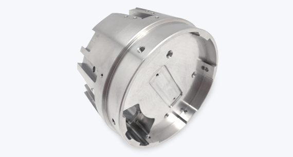
5. Live‑Tool Turning
In addition to milling, Konlida offers live‑tool CNC turning for cylindrical parts. Live tooling allows off‑centre holes, slots, flats, and other features to be machined parallel or perpendicular to the part's Z‑axis – all in a single setup.
Turned parts (shafts, pistons, fittings) start as round bar stock. The same design rules generally apply as for milled parts, but note that we do not currently turn plastic materials (plastics are handled through milling or injection moulding).
For turned part design guidance, refer to our CNC turning design guidelines [Internal Link: /services/cnc-machining-service/cnc-turning/design-guidelines/].
6. 3‑Axis vs. 5‑Axis Milling
Konlida offers both 3‑axis and 5‑axis milling.
3‑axis machining:
- The workpiece is gripped from the bottom
- Features are cut from up to 6 orthogonal sides
- For parts larger than 254 mm × 178 mm, only the top and bottom can be machined (no side setups)
5‑axis indexed milling:
- Machining from any number of non‑orthogonal sides
- Dramatically reduces setups and improves accuracy for complex geometries
- Often uses round stock, requiring careful positioning within the raw material volume
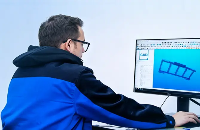
If your part requires complex angled features or multiple setups, 5‑axis machining can significantly reduce production time and improve accuracy. To find out which approach is best for your part, simply upload your CAD model for a free DFM analysis and quote.
Summary: Design Checklist for CNC Machining
| Consideration | Recommended Practice |
|---|---|
| Hole depth | Limit to ≤ 6× tool diameter where possible |
| Threading | Use thread milling; specify UNF/UNC/metric |
| Text | Engraved, ≥0.5 mm stroke, Sans‑Serif font |
| Wall height | Keep height‑to‑width ratio ≤ 4:1 |
| Turning | Use live‑tool lathes for complex cylindrical parts |
| Milling strategy | Use 5‑axis for complex geometries, 3‑axis for simpler parts |
Need Help with Your Design?
Our applications engineering team is experienced in supporting European customers with DFM (Design for Manufacturability) reviews. We can help you optimise your part design for cost, lead time, and quality – often with suggestions that reduce machining time by 20–40%.