Maximise part quality, reduce costs, and navigate design challenges using standardised tolerances for machined parts
In 1801, Eli Whitney – inventor of the cotton gin – demonstrated to the United States Congress a revolutionary concept: all components required for an assembly should be produced to a precise set of standards, i.e. specific dimensions and tolerances. This would ensure, for example, that the firing pin or gun barrel from one musket would fit any other musket. His idea helped pave the way for the Second Industrial Revolution and what became known as the American System of Manufacturing.
Today, component interchangeability and dimensional tolerancing are accepted fundamentals of manufacturing. However, misapplication of tolerances can cause numerous problems. Overly tight tolerances may require secondary operations such as grinding or EDM, unnecessarily increasing cost and lead time. Tolerances that are too loose, or incompatible with mating parts, can make assembly impossible, leading to rework or even scrapping the finished product.
To help you avoid these issues, this design guide provides practical recommendations for applying tolerances correctly. It also explains common tolerance callouts and introduces the principles of Geometric Dimensioning and Tolerancing (GD&T) in line with ISO 1101 (the international equivalent of ASME Y14.5).
Standard Tolerances for CNC Machining
At Konlida Precision Technology, we offer several tolerance grades depending on part quantity, geometry, and customer requirements.
Rapid Prototyping & Standard Production Machining
- Standard tolerance (metals): ISO 2768‑1‑1989‑f
- Standard tolerance (plastics): ISO 2768‑1‑1989‑m
- Typical linear tolerance: ±0.13 mm
Precision Machining (High‑Accuracy Option)
- Linear tolerance: ±0.051 mm
- Reamed hole diameter: achievable down to ±0.0127 mm
- Feature location (machined on the same side): ±0.051 mm
Depending on part geometry and material, even tighter tolerances are often achievable. Please specify your requirements clearly when uploading your design files.
Note: The above are bilateral tolerances. If you need unilateral tolerances (e.g. +0.00 / -0.10 mm) or limit tolerances (e.g. 10.00 / 9.90 mm), please indicate them on your drawing.
Tolerancing Guidelines
Units and Decimal Places
- We accept both metric (mm) and imperial (inch) units, but metric units are strongly preferred for European customers.
- Avoid unnecessary decimal places. For example, use 1.00 mm rather than 1.0000 mm unless there is a compelling reason.
Surface Roughness
- Standard milled surfaces: Flat surfaces Ra ≤ 1.6 µm, curved surfaces Ra ≤ 3.2 µm or better.
- For cosmetic metal parts, light bead blasting can improve appearance.
- If you require a smoother finish (e.g. Ra 0.8 µm), please note it on your design – we will do our best to accommodate.
For more examples, refer to our CNC Surface Finish Guide.
Geometric Tolerancing (GD&T / ISO GPS)
Beyond linear dimensions and hole positions, the geometric relationship between part features is critical. Konlida supports geometric tolerancing in accordance with ISO 1101. Below are commonly used symbols:
True Position (Position)
Traditional coordinate tolerancing defines hole location by X and Y distances from two perpendicular edges. In GD&T, true position is defined relative to a set of reference datums, optionally with Maximum Material Condition (MMC) or Least Material Condition (LMC) – offering more precise control for assembly fit.
Flatness
Milled surfaces are generally flat, but internal material stress or clamping forces can cause warpage – especially on thin‑walled or plastic parts. Flatness defines two parallel planes within which the entire surface must lie.
Cylindricity
A ±0.13 mm linear tolerance on a 10 mm hole could theoretically allow it to become oblong (e.g. 9.95 mm in one direction, 10.05 mm in another). Cylindricity requires the hole surface to lie between two concentric cylinders, ensuring true roundness.
Concentricity
The rings of a bullseye are concentric, just as a wheel is concentric to its axle. If a drilled or reamed hole must be perfectly coaxial with a counterbore or circular boss, concentricity is the correct callout.
Perpendicularity
Perpendicularity controls the maximum deviation of a horizontal machined surface from a nearby vertical surface. It can also be used to ensure the squareness of a turned shoulder to an adjacent diameter or the part’s central axis.
Other geometric characteristics – including parallelism, straightness, profile, and angularity – are defined in ISO 1101.
Important: If your design requires geometric tolerancing, please provide a 2D engineering drawing with clear datum references and tolerance values when you upload your CAD model. Our application engineers will manually review the drawing and provide a quotation.
Quality Control & Documentation
Konlida offers comprehensive quality assurance services to meet European requirements for traceability and compliance:
- First Article Inspection (FAI) – in line with ISO 9001 / AS9100D
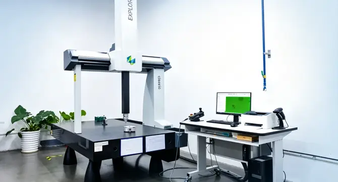
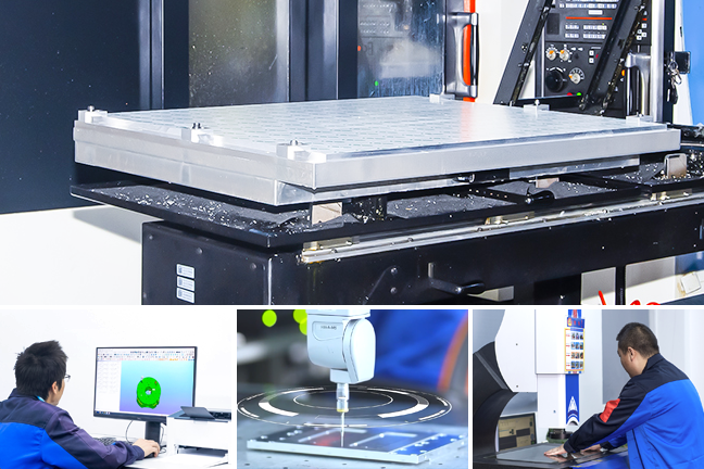
- CMM inspection – using Hexagon coordinate measuring machines for full dimensional reporting
- Material certificates – including raw material test reports and heat/lot numbers
- PPAP (Production Part Approval Process) – available upon request (especially for automotive customers)
- Certificate of Conformance (CoC) – issued to your specified standards
Please indicate any required quality documentation when requesting a quote. Our quality team will tailor the inspection plan accordingly.
Choosing the Right Machining Option
Konlida offers two flexible machining paths to suit different project needs:
1. Automated Rapid Machining
- Best for: Prototypes, small batches, standard tolerances
- Advantages: Online quoting, automated DFM analysis, short lead times (as fast as 3–5 days)
- Tolerances: ISO 2768‑f / ‑m or ±0.13 mm
2. High‑Precision / High‑Volume Machining
- Best for: Complex geometries, tight tolerances (≥ ±0.051 mm or stricter), GD&T requirements
- Process: Manual review of 2D drawings and GD&T callouts – slightly longer quoting time
- Extended capabilities: Wire EDM, hole‑popping EDM, grinding, boring (available through our partner network)
Our application engineering team is ready to advise you on the best balance of quality, cost, and lead time for your specific project.