

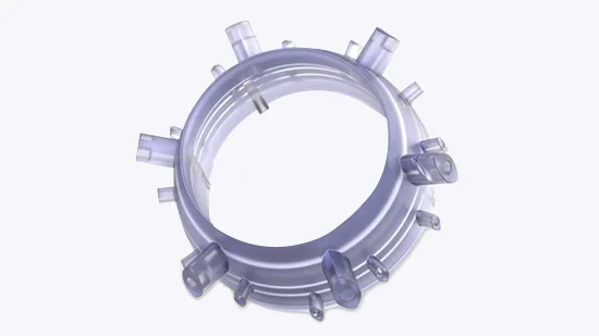

Designing Liquid Silicone Rubber Prototypes and Components
Learn how to optimise LSR parts with 6 simple design considerations
Content in this Article
- Dimensions
- Wall and Rib Thickness
- Shrink and Flash
- Parting Lines
- Undercuts
- Overmolding and Insert Molding
- Part Ejection
- LSR Capabilities at Konlida
Introduction
Liquid silicone rubber (LSR) is available among our injection moulding capabilities. LSR moulding shares many similarities with conventional injection moulding, but there are a few notable differences. Unlike thermoplastic resin, which is melted before injection, LSR is a two‑part thermoset compound that is chilled before being injected into a heated mould and ultimately cured into a final part. Since LSR is a thermosetting polymer, its moulded state is permanent—once it is set, it cannot be melted again like a thermoplastic.
🔗 Explore our Liquid Silicone Rubber Moulding service →
LSR is a strong, elastic material with excellent thermal, chemical, and electrical resistance. LSR parts also maintain their physical properties at extreme temperatures and can withstand sterilisation. LSR is biocompatible, making it well suited for products that have skin contact. These benefits lend themselves to automotive, medical, and food appliance industries, typically in the form of seals, gaskets, valves, and cables.
🔗 View LSR materials in our Material Comparison Guide →
Designing parts for LSR and thermoplastics is broadly similar, but there are some LSR‑specific guidelines to consider.
1. Dimensions
We allow for a maximum LSR part size of:
| Dimension | Maximum |
|---|---|
| Length | 304 mm |
| Width | 203 mm |
| Height | 100 mm |
| Depth from parting line | ≤ 50 mm |
| Maximum surface area | 422.6 cm² |
| Maximum part volume | 426 cc |
Note that deeper parts are limited to a smaller outline.
🔗 See our full Injection Moulding capabilities
2. Wall and Rib Thickness
LSR typically fills thin wall sections with minimal challenges. Walls as thin as 0.3 mm are possible over smaller areas, and down to 0.38 mm over larger areas, depending on wall size and the location of adjacent thicker sections.
Key guidelines:
- Rib thickness should be 0.5 to 1.0 times the adjoining wall thickness
- LSR accommodates variations in wall thickness well
- Sink marks are almost non‑existent – one of LSR's key advantages over thermoplastics
This makes LSR particularly forgiving for parts with complex geometry or uneven wall sections.
🔗 Refer to our Design Guidelines for LSR for more detailed rules →
3. Shrink and Flash
Shrinkage:
- The shrink rate on LSR is fairly high but consistent throughout the entire part
- Expected tolerance: 2.5% (0.025 mm per mm)
Flash:
- LSR tends to flash easily during moulding – in gaps as small as 0.005 mm
- We help reduce flash by incorporating additional features into the mould design
🔗 Learn more about our Quality control procedures
4. Parting Lines
Simplify and minimise parting lines in your design to achieve cleaner LSR parts more quickly. Complex parting lines increase the risk of flash and add time to both mould manufacturing and post‑processing.
🔗 View our Injection Moulding Design Tips →
5. Undercuts
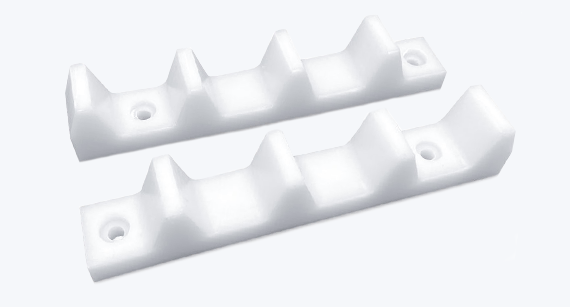
LSR can be moulded to accommodate parts with undercuts, which are manually removed by a press operator. Mechanical tooling actions to release undercuts are selectively available.
Important:
- LSR tends to tear fairly easily at sharp edges
- When designing interior features, add fillets or radii to prevent tearing at sharp edges
- This is especially critical when using manually removed undercuts
For parts with complex undercuts, consult our applications engineering team early in the design phase.
🔗 Contact our Applications Engineering Team
6. Overmolding and Insert Molding
LSR materials can also be used for overmoulding and insert moulding purposes.
Overmoulding
LSR is often used for overmoulding, which allows an additional layer of resin to be added to an existing moulded part – providing a combination of characteristics that no single material can offer. Common applications include:
- Adding a soft, functional, hand‑friendly layer over a hard substrate
- Enhancing appearance or cosmetics with a different colour or finish
Examples range from medical devices and hand tools to toothbrushes and oven knobs.
🔗 Explore our Overmoulding capabilities →
Insert Moulding
Insert moulding adds strength and durability to parts, typically by reinforcing pivotal points with metal – a brass bearing journal or stainless steel threaded insert – or a high‑temperature plastic material.
Recommended insert materials for LSR moulding:
- Valox (PBT)
- PEI (Ultem)
- PEEK
Important considerations:
- There usually needs to be mechanical bonding features when insert moulding LSR onto other parts, as LSR generally does not chemically bond
- We do not allow the use of primers to create a chemical bond
🔗 Learn more about Insert Moulding →
🔗 View PEEK and PEI material properties →
7. Part Ejection
Ejector pins are normally not used during LSR moulding due to the material's tendency to flash.
Design considerations:
- Parts should be designed so they can be retained on one half of the mould when it opens at the end of the moulding cycle
- The part is then manually de‑moulded, often with air assistance
This manual removal process is one of the key differences between LSR and thermoplastic moulding – and it should be considered early in the design phase.
LSR Capabilities at Konlida
| Parameter | Specification |
|---|---|
| Maximum part size | 304 mm × 203 mm × 100 mm |
| Maximum part volume | 426 cc |
| Minimum wall thickness | 0.3 mm (small areas) / 0.38 mm (large areas) |
| Linear tolerance | ±0.08 mm (plus ±0.01 mm/mm) |
| Shrinkage | 2.5% (consistent) |
| Typical lead time | 3 weeks |
| Typical order quantity | 25 to 5,000+ parts |
Finished part surface finishes available:
- Standard fine finishes (PM‑F0, PM‑F1)
- SPI standard finishes (SPI‑C1, SPI‑A2)
- Textured finishes (PM‑T1, PM‑T2)
🔗 View our Injection Moulding Production services
Summary
Designing for LSR requires attention to a few specific considerations, but the material's forgiving nature – particularly its tolerance for wall thickness variation and its resistance to sink – makes it an excellent choice for complex elastomeric parts.
Six key takeaways for LSR design:
| Consideration | Recommendation |
|---|---|
| Dimensions | Maximum 304 × 203 × 100 mm |
| Wall thickness | ≥ 0.3 mm; uniform thickness not critical |
| Shrinkage | 2.5% – account for in design |
| Flash | Minimise with simple parting lines |
| Undercuts | Use fillets/radii to prevent tearing |
| Ejection | Design for manual removal – no ejector pins |