

The most obvious approach to undercuts is side-actions—mold pieces that act from the outside of the part, moving perpendicular to the direction of mold opening. These produce side-facing features in a closed mold and then automatically withdraw, allowing the A-side mold half to withdraw as the mold opens, and the part to be ejected from the B-side. In Figure 1, a side-action cam produces the door, sealing against the B-side core as the mold fills and then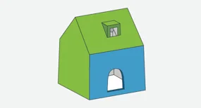 withdrawing to allow ejection. A similar technique could produce non-through indentations that would otherwise act as undercuts.
While side-actions are a relatively simple solution, there are a couple of things to keep in mind when using them:
They must open perpendicular to the direction of mold opening. This would be simple if part walls didn’t have to be drafted and were always positioned vertically. Since walls are not always conveniently oriented, care must be taken to ensure that side-actions operate (and are, themselves, drafted) perpendicular to the direction of mold opening and not necessarily perpendicular to the surfaces on which they live.
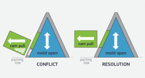
Orientation matters. Imagine the window in Figure 1 as a skylight in the roof rather than a dormer window (see Figure 2). A window perpendicular to the angled roof would be partially trapped as the cam opens sideways. Fortunately, most CAD programs allow you to define the face or plane to which a feature should be oriented and drafted. In this case, in creating the skylight you would simply orient perpendicular to the plane of the parting line rather than that of the roof.
While cams are typically used to produce small features, they can also be used to produce large portions of a part. In Figure 3, we see a part’s top and bottom formed by A- and B-side mold halves, with its entire circumference formed entirely by two cams.
The design of side-actions can significantly impact part quality. If a side-action is not properly drafted, it can cause cosmetic defects in injection moulding such as drag marks or flash—particularly at the sealing surfaces where the cam meets the core.
In some cases, you can eliminate the cost and complexity of side-actions by using simple two-part molds with strategically placed sliding shutoffs. This is an area in which faces of the A- and B-side mold halves move parallel to one another as the mold opens.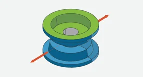
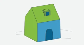
If we remove the bottom sill from the door of the house, as shown in Figure 4, we can produce the features solely by the interaction of the A- and B-side mold halves. When the mold is closed, a door‑shaped pad extending from the B‑side mold half seals against the wall of the A‑side mold half. Because there is no sill under the door, the pad is not trapped and can exit through the bottom of the door as the mold opens.
Key considerations for sliding shutoffs:
Draft requirements. Unlike a door formed by a side‑action, which is drafted toward the outside of the house, a door formed by the B‑side mold half is drafted toward the bottom of the house to facilitate part ejection. Similarly, the sliding shutoff itself—the area of the B‑side mold half where the pad that forms the door meets the inside of the A‑side mold half—must be drafted to a minimum of 3 degrees. This allows a tight seal when the mold is clamped shut for injection and prevents wear of the mold surfaces as the mold opens. Shutoff wear can lead to leakage of resin between the mold faces, resulting in flash which is unsightly and may interfere with part function.

Applications. Sliding shutoffs can be used to produce a variety of other useful features. One is a clip (Figure 5). By its very nature, the hook at the end of a clip is specifically designed to catch, so the area under it would normally be an undercut. Creating a hole in the “floor” under the hook achieves the same end result as removing the sill under the door. In this design, it allows a rectangular‑shaped pad of one mold half to extend up through the floor to create the bottom of the hook and the recessed face of the clip. The rectangular‑shaped pad shuts off against the walls of the other mold half, which produces the rest of the clip.
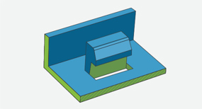
Another useful feature that can be formed using shutoffs is a through‑hole perpendicular to the direction of mold opening (Figure 6). By removing alternating sections of the hole’s wall, you can allow each mold half to form, alternately, inside and outside surfaces of the channel. The two mold halves meet at multiple points along the length of the through‑hole and must be drafted at each of these points.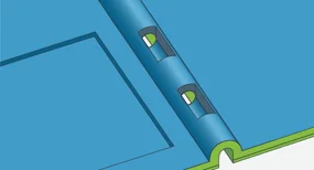
For more on clip design and the role of draft in ensuring proper function, see our guide on designing more effective clips on plastic injection‑moulded parts .
We’ve shown how removing a sill can eliminate the need for side‑actions, but there are also instances in which a fully surrounded through‑hole —a window, for example—can be produced by sliding shutoffs. This is achieved by adding an increased amount of draft to a wall to allow the window to be formed partially by each of the two mold halves.
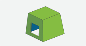
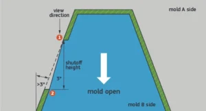
The window in Figure 7 is formed by the sliding shutoff shown in Figure 8. In this case, the shutoff between the two mold halves angles across the window. The top edge of the window is formed by the B‑side mold half; the bottom edge is formed by the A‑side mold half. The two mold faces must be drafted by at least 3 degrees where they shut off. To allow this, the part wall itself must be drafted by more than 3 degrees. The additional amount by which the wall must be drafted depends on the part geometry.
How to evaluate shutoff feasibility:
When looking down on your shutoff, can you clearly see the mating edges? If one edge is hidden under the other, you cannot use this shutoff design.
Is the angle between the mating edges drafted at 3 degrees or greater?
In Konlida’s injection molding process, cams cannot form undercuts on non‑exterior surfaces. In many cases, however, undercuts on interior surfaces can be formed using pickouts. These are inserts that are part of the mold when resin is injected, but are ejected with the part and then removed from the part, leaving undercut features in their place. By filling the undercut and becoming, temporarily, an element of the part, a pickout eliminates ejection problems.
Key considerations for pickouts:
Cost and cycle time. Pickouts add complexity to the molding process because they must be manually or automatically removed from the part after ejection. This adds cycle time and labor cost compared to side‑actions or sliding shutoffs. However, for interior undercuts that cannot be formed by other methods, pickouts may be the only viable solution.
Design for removal. The pickout must be designed so that it can be easily removed from the finished part. This typically requires some form of access or a feature that allows the operator to grip and extract the pickout without damaging the part.