

Design for Sheet Metal Fabrication Toolkit
Get in-depth design advice to optimize your parts for sheet metal fabrication. Designing with fabrication requirements in mind can accelerate production time and reduce cost throughout the product lifecycle.
Optimizing Part Design for Sheet Metal Fabrication
There are many design elements involved in creating parts for sheet metal fabrication—design for cost, quality, assembly, and manufacturability. Navigating that landscape can be challenging at times. At Konlida, we provide automated design analysis on CAD models that highlights features in your part design that can be adjusted for manufacturability. It’s a great design resource right at your fingertips. To keep design advisories at a minimum and optimize part design, we created this helpful kit of sheet metal fabrication resources.
Designing Complex Features for Sheet Metal Parts
- 8 Rules for Converting Solid 3D Designs to Flat Sheet Metal
- The Basics of Bend Radii in Sheet Metal
- Integrating Hardware into Sheet Metal Design
- Working with Sheet Metal Tolerances
- Designing Sheet Metal Notches, Tabs, and Slots
Navigating Critical Sheet Metal Advisories
- Minimum Flange Lengths
- Placing Features Near Bends
- Bend Radius Out of Tooling Range
- Hardware Insert and Sheet Stock Compatibility
Designing Complex Features for Sheet Metal Parts
Minimum Flange Lengths
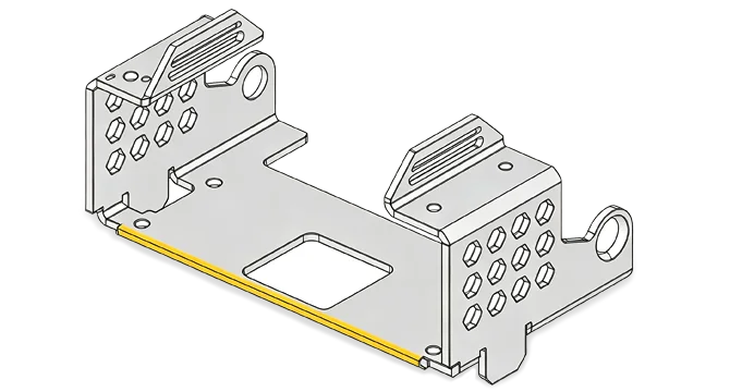
Minimum flange lengths are required to hold a workpiece between the top and bottom die in the press brake. The necessary flange length for forming is dependent on material type, material thickness, and bend radius. Refer to the table below for length guidelines per Konlida tooling requirements.
| Material Thickness | Material type | ||
|---|---|---|---|
| Aluminum / Copper | CRS / Galv. / Galvnl. | Stainless Steel | |
| .024 -.050 in. | 3.0x material thickness + bend radius | 3.5x material thickness + bend radius | 3.5x material thickness + bend radius |
| .060 -.090 in. | 2.5x material thickness + bend radius | 2.75x material thickness + bend radius | 2.75x material thickness + bend radius |
| .100 -.134 in. | 2.5x material thickness + bend radius | 2.5x material thickness + bend radius | 2.5x material thickness + bend radius |
| .160+ | 3.0x material thickness + bend radius | 3.5x material thickness + bend radius | 4.0x material thickness + bend radius |
Additional design considerations:
- Choose a smaller internal bend radius.
- For alternative fabrication options, schedule a time to review your design with a sheet metal applications engineer.
Placing Features Near Bends
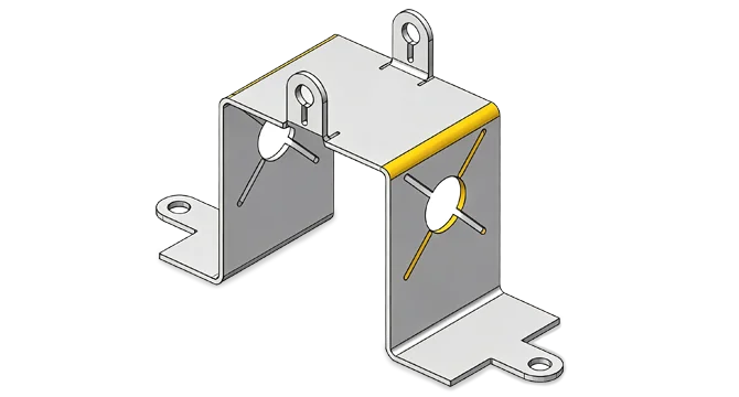
Feature placement in sheet metal design unlocks complexity and part functionality, however as sheet metal stretches during forming, features can distort if placed too close to bends. Like minimum flange length, feature proximity to a bend is dependent on material type, material thickness, and bend radius. Refer to the table below for distance guidelines.
| Material Thickness | Material type | ||
|---|---|---|---|
| Aluminum / Copper | CRS / Galv. / Galvnl. | Stainless Steel | |
| .024 -.050 in. | 3.0x material thickness + bend radius | 3.5x material thickness + bend radius | 3.5x material thickness + bend radius |
| .060 -.090 in. | 2.5x material thickness + bend radius | 2.75x material thickness + bend radius | 2.75x material thickness + bend radius |
| .100 -.134 in. | 2.5x material thickness + bend radius | 2.5x material thickness + bend radius | 2.5x material thickness + bend radius |
| .160+ | 3.0x material thickness + bend radius | 3.5x material thickness + bend radius | 4.0x material thickness + bend radius |
Additional design considerations:
- Choose a smaller internal radius.
- For alternative fabrication options, schedule a time to review your design with a sheet metal applications engineer.
Bend Radius Out of Tooling Range
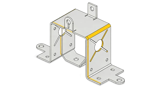
Konlida provides a range of internal bend radius tooling options between 0.01 in. and 1 in.
Note: As Konlida uses primarily air bending technology, the actual radius on a physical part may vary slightly from the tool used during forming.
| Internal Radius Tooling Options | |||
|---|---|---|---|
| 0.01 in. | 0.09 in.* | 0.25 in. | 0.625 in. |
| 0.03 in.* | 0.12 in.* | 0.375 in. | 0.75 in. |
| 0.06 in.* | 0.188 in. | 0.5 in. | 1 in. |
*If lead time is a priority, consider one of these options in your part design
- For parts with internal radii greater than 1 inch, Konlida will use a technique called “bump” forming (multiple tooling lines will be present).
Hardware Insert and Sheet Stock Compatibility
Konlida carries an extensive library of PEM® fasteners. Follow these two guidelines for successful compatibility between the material of the part and the material of the hardware insert:
- The sheet metal material type must be softer than the material of the hardware being installed.
- Inserts grip the sheet metal during the installation process, therefore enough grip is required to ensure correct seating.
Refer to the table below as a reference guide for compatible insert to material type.
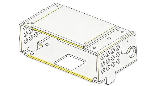
| Part Material | Common Hardware Types | Standard hardware materials | |||
|---|---|---|---|---|---|
| Clinch Nuts | Studs/Pins | Standoffs | Other | ||
| Aluminum 5052, Aluminum 6061 | CLA | FHA | SOA, BSOA, TSOA | LKA, RAA | Aluminum |
| CLS, CLSS, SMPS | FHS, FHLS, TPS | SOS, BSOS, TSOS | F, FE, FEX, LKS, AC, TDS | Stainless Steel | |
| Cold Rolled Steel (CRS), Pre-plated Steel (galvanized, galvanneal) | S, SS | FH, FHL, TFH | SO, BSO, TSO | LK, PL, AS, CFN | Steel |
| Stainless Steel 304, Stainless Steel 316 | SP, SMPP | FH4, TP4, FHP | SO4, BSO4, TSO4 | F4, A4 | 400 Series Stainless Steel |